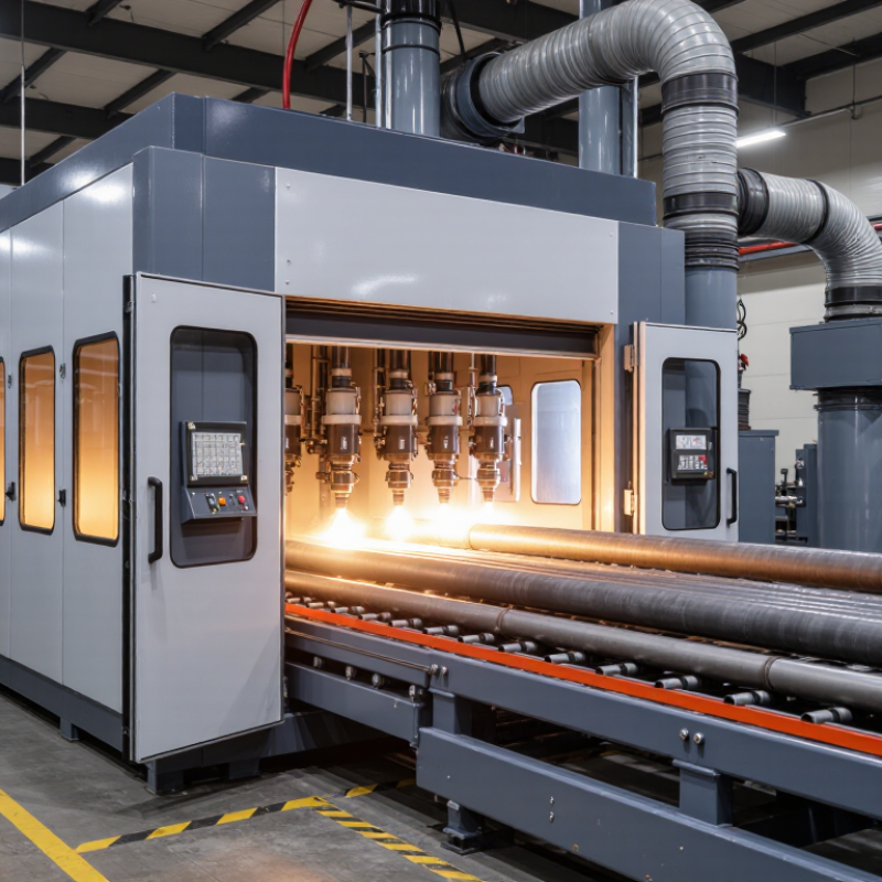
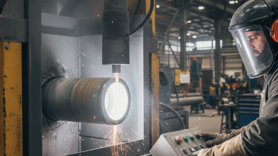
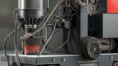
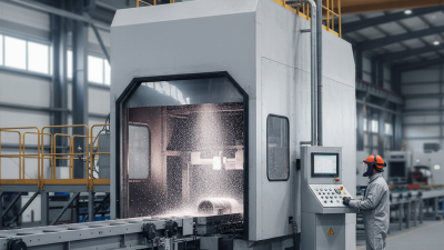
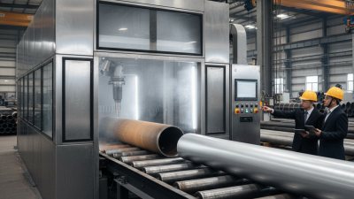
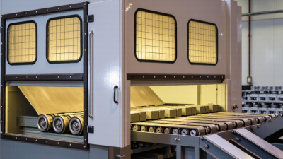
Selecting the right Pipe Blasting Machine is more than comparing pressure, price, and delivery time. It is a decision about surface quality, worker protection, production rhythm, and long-term maintenance. Grand View Research and MarketsandMarkets both identify rising demand for automated surface-treatment equipment, driven by infrastructure renewal, energy projects, and stricter coating-performance expectations. However, market growth does not make every machine suitable for every pipe.
A practical evaluation should begin with pipe diameter, length, material, coating condition, and daily production volume. A machine designed for small carbon-steel pipes may struggle with thick scale inside large-diameter tubes. Watch the abrasive flow. Inspect the nozzle position. Check whether the system maintains a consistent blast pattern around weld seams and curved surfaces. AMPP coating guidance emphasizes that surface preparation strongly influences coating adhesion and service life. That detail is easy to underestimate.
Safety cannot be treated as a final checkbox. OSHA sets a respirable crystalline silica permissible exposure limit of 50 micrograms per cubic meter, averaged over eight hours, when applicable. Dust collection, enclosure design, ventilation, and operator protection therefore deserve careful comparison. The best Pipe Blasting Machine should also offer accessible wear parts, measurable cleaning results, and documented maintenance procedures. These features may seem ordinary. They often determine real operating costs.
There is no universal winner. A larger cabinet may improve throughput but consume more energy and floor space. Automated loading can reduce labor, yet it may complicate setup. Buyers should request trial results using their own pipes. Specifications look precise, but field performance can differ. That uncomfortable gap deserves attention.
Choosing the best pipe blasting machine starts with accurate pipe measurements. Record the internal diameter, outside diameter, total length, and wall condition. A few millimeters can affect nozzle clearance and abrasive flow.
Diameter controls the blasting head, nozzle arrangement, and cleaning pattern. Narrow pipes need compact tooling and careful abrasive control. Larger pipes may require multiple nozzles or a rotating head. Length matters too. A long pipe needs stable support, smooth cable movement, and consistent abrasive recovery. I have seen operators select equipment by diameter alone, then struggle with uneven cleaning near the far end. That assumption is easy to miss.
Throughput should be measured in m²/h, not only pipes per hour. Calculate the pipe surface area, then compare it with the machine’s practical capacity. The rated figure may exclude loading, repositioning, nozzle changes, and filter cleaning. Ask for test data on a similar diameter, length, coating, and surface condition. Real results are more useful than a brochure number. Keep some margin. A machine running continuously at its limit may produce inconsistent profiles and faster wear.
For reliable selection, inspect the abrasive recovery system and dust filtration. These systems influence visibility, maintenance time, and workplace cleanliness. Measure one sample pipe before purchasing. Then test the blasted surface for coverage and profile. My own preference is to accept slightly lower m²/h when it delivers even preparation throughout the pipe. Faster is not always better.
How to Choose the Best Pipe Blasting Machine?
Set the cleanliness target before comparing machine specifications. ISO 8501-1 Sa 2½ and SSPC-SP 10/NACE No. 2 describe a near-white metal surface. Visible oil, grease, mill scale, rust, and old coating must be removed. Only slight shadows, stains, or streaks may remain. This target matters because the NACE IMPACT study estimated global corrosion costs at $2.5 trillion annually, equal to about 3.4% of global GDP.
A suitable pipe blasting machine must deliver this finish around the entire circumference. Check nozzle coverage, abrasive flow, rotation speed, and dust extraction. A narrow shadow beneath a pipe can reveal uneven cleaning. It is easy to miss. Lighting and surface angle also affect visual inspection. Do not rely on appearance alone. ISO 8501-1 defines visual cleanliness, while surface profile requires separate measurement under relevant ASTM or SSPC procedures.
Site records should show abrasive type, pressure, line speed, ambient conditions, and inspection results. These details support repeatability and traceability. Experienced inspectors also check the surface after handling, because fingerprints, flash rust, or condensation can undermine preparation. A machine may reach Sa 2½ during a trial, yet fail during continuous production. That is an uncomfortable possibility. Require a full-length pipe test, measure the profile, and review dust levels before approval. Temperature control is not always perfect, either. Poor assumptions here can create coating failures later.
| Selection Dimension | Recommended Target or Requirement | Why It Matters for Pipe Blasting | Machine Selection Guidance | Verification Method |
|---|---|---|---|---|
| Primary surface-cleanliness standard | ISO 8501-1 Sa 2.5: Very Thorough Blast-Cleaning | Most visible mill scale, rust, coatings, and foreign matter must be removed. Only light staining, such as slight shadows, streaks, or discoloration, may remain. | Choose a machine capable of producing consistent abrasive coverage around the complete pipe circumference, including weld areas and difficult-to-reach zones. | Compare the blasted surface with the reference photographs in ISO 8501-1 under suitable lighting. |
| Alternative cleanliness standard | SSPC-SP 10 / NACE No. 2: Near-White Metal Blast Cleaning | At least 95% of each unit area must be free of visible oil, grease, dust, dirt, mill scale, rust, coatings, oxides, corrosion products, and other foreign matter. Minor staining may remain on the balance of the surface. | Use controlled abrasive flow, stable blast pressure, and sufficient dwell time to avoid untreated bands or shadowing along the pipe. | Inspect representative areas visually according to the written project specification and the applicable visual reference standard. |
| Relationship between Sa 2.5 and SSPC-SP 10 | Generally comparable cleanliness level, but not automatically interchangeable | The standards describe similar near-white blast-cleaning results, but their wording, inspection procedures, and project requirements can differ. | Set the machine and acceptance procedure against the exact standard named in the contract, coating specification, or purchase order. | Record the specified standard, inspection criteria, inspector, lighting conditions, and acceptance result. |
| Pipe outside diameter range | Define the minimum and maximum pipe diameter before selection | Pipe diameter affects nozzle position, abrasive impact angle, rotation speed, and the overlap between adjacent blast passes. | Select adjustable tooling, roller spacing, nozzle position, and rotation controls that cover the full diameter range without creating shadow areas. | Run test pieces at the smallest and largest diameters and inspect the complete circumference. |
| Pipe length and handling | Match the machine layout to the longest and heaviest pipe | Long or heavy pipes require stable support to prevent vibration, deflection, uneven rotation, and inconsistent abrasive coverage. | Check load capacity, support spacing, entry and exit clearance, transfer equipment, and safe handling provisions. | Confirm rated load, support arrangement, and dimensional compatibility using the equipment documentation. |
| Blast media selection | Use an abrasive compatible with the coating system and substrate | Abrasive type and size influence cleaning speed, surface profile, dust generation, embedded particles, and the final coating bond. | Choose a machine with abrasive recovery, separation, and metering systems suitable for the selected media. Avoid abrasive contamination and excessive breakdown. | Check abrasive condition, cleanliness, particle-size distribution, and compliance with the project specification. |
| Surface profile | Specify a numerical profile range separately from Sa 2.5 or SSPC-SP 10 | Cleanliness standards do not by themselves define the required anchor profile. The correct profile depends on the coating manufacturer and service environment. | Provide adjustable blast pressure, nozzle distance, abrasive flow, and pipe rotation speed to achieve the specified profile consistently. | Measure using an approved surface-profile comparator, replica tape, or electronic depth gauge, as required by the project specification. |
| Blast pressure and abrasive flow | Establish parameters through a controlled trial rather than using one universal setting | Pressure and abrasive flow depend on steel condition, coating thickness, abrasive type, nozzle size, and required production rate. | Choose equipment with stable pressure control, calibrated abrasive metering, and accessible operating adjustments. | Document trial settings and verify cleanliness, profile, production rate, and abrasive consumption. |
| Coverage and rotation uniformity | No visible unblasted bands, shadowing, or untreated weld zones | Uneven coverage can cause premature coating failure even when most of the pipe appears clean. | Prioritize synchronized pipe rotation, nozzle movement, overlapping passes, and consistent standoff distance. | Inspect the full circumference, pipe ends, welds, transitions, and other geometrically difficult areas. |
| Dust and abrasive recovery | Control airborne dust and prevent abrasive contamination | Dust can obscure inspection, contaminate the prepared surface, reduce visibility, and increase worker exposure. | Select an enclosed blast chamber with effective ventilation, dust extraction, abrasive separation, and collection capacity. | Check visibility inside the chamber, dust collector performance, housekeeping, and recovered abrasive quality. |
| Post-blast dust cleanliness | Surface must be free of loose dust before coating | Residual dust can interfere with coating adhesion and may be redistributed during handling or transport. | Include suitable blow-off, vacuuming, or cleaning procedures and minimize recontamination between blasting and coating. | Use the dust assessment method required by the project specification, such as pressure-sensitive tape evaluation. |
| Soluble salt contamination | Set a project-specific maximum contamination level | Sa 2.5 and SSPC-SP 10 address visible surface cleanliness, not the complete removal or acceptance of soluble salts. | Provide pre-cleaning and inspection controls when pipes have been exposed to marine, chemical, or contaminated environments. | Measure soluble salts using an approved field test method and compare the result with the coating specification. |
| Surface condition before blasting | Remove oil, grease, and heavy contaminants before abrasive blasting | Blasting can spread oily contamination or drive it into the surface instead of removing it. | Use a defined degreasing and pre-cleaning stage before the pipe enters the blasting chamber. | Perform a visual inspection and, where required, use a suitable solvent or contamination test. |
| Production capacity | Size capacity from required pipe length, diameter, cleanliness target, and available operating hours | A high nominal throughput does not guarantee the required surface preparation quality under actual operating conditions. | Compare effective production rate, changeover time, abrasive replenishment, maintenance intervals, and inspection delays. | Validate output using a representative production trial while maintaining Sa 2.5 or SSPC-SP 10 acceptance. |
| Inspection and traceability | Document cleanliness, profile, dust, salts, settings, and inspection results | Traceable records help demonstrate that the prepared surface met the coating and project requirements. | Select equipment that supports repeatable settings, calibration, alarms, data recording, and easy inspection access. | Maintain inspection reports linked to pipe identification, date, operator, machine settings, and acceptance status. |

How to Choose the Best Pipe Blasting Machine?
For many pipe lines, the practical starting point is 6–8 bar air pressure. This range supports stable abrasive flow without excessive dust or media waste. AMPP surface-preparation guidance stresses that pressure, nozzle distance, and abrasive type must be controlled together. Pressure alone does not guarantee a clean surface. I have seen operators increase pressure when rust remains, yet the real problem was an uneven nozzle angle. ISO 8501-1 also reminds inspectors to judge cleanliness visually against defined preparation grades, not by pressure readings.
Wheel systems require a different comparison. Turbine speed commonly falls near 2,000–3,000 rpm, while abrasive velocity may approach 60–80 m/s, depending on wheel diameter and design. Higher speed can improve production, but it may also thin sharp edges and increase abrasive consumption. A 2024 industrial equipment market review by Grand View Research links automation with higher productivity, but productivity figures vary widely by pipe diameter, coating condition, and loading method. Treat those figures carefully. One impressive number can hide difficult maintenance.
Tips: Test a short pipe section first. Record air pressure, wheel speed, travel rate, and abrasive flow. Check the profile with a surface replica or suitable gauge. Compare the result with the specified ISO 8501-1 grade. Keep a small margin below the maximum setting. It is often safer. Then inspect dust collectors, seals, and wheel balance before increasing output.
This comparison uses representative operating points for pipe blasting systems. Air pressure is shown in bar, while wheel speed is converted to abrasive wheel tip speed using a 400 mm wheel diameter. Higher pressure can improve abrasive delivery, while higher wheel speed increases impact energy and removal capacity. Always confirm the operating range against the machine specification and pipe material.
Choosing a pipe blasting machine starts with the abrasive, not the machine size. Steel grit G25 creates a deeper, more aggressive profile on heavy scale and thick coatings. G40 is finer and can produce a more even surface on smaller pipes or thinner coatings. The correct grade depends on coating thickness, pipe diameter, steel hardness, and the required anchor profile. A trial blast on a short pipe section is safer than relying on a supplier’s chart.
Recovery performance matters just as much. A practical system should separate usable grit from dust, paint flakes, and broken particles. A well-adjusted reclaim floor, separator, and dust collector can reduce abrasive waste and keep the blast pattern stable.
In many workshops, a recycling rate near 85–95% is achievable, but this figure changes with pipe shape, operator settings, and abrasive breakdown. Measure actual consumption per pipe batch. Do not trust one impressive percentage.
I once treated recovery rate as a single machine specification. That was too simplistic. Check the recovered grit after several cycles. If G25 becomes rounded too quickly, the surface profile may weaken. If G40 carries excessive dust, the separator may need adjustment. Watch the details: uneven brightness, blocked nozzles, rising dust, and longer blasting time. These signs often reveal a poor abrasive match before production quality visibly drops.
A suitable pipe blasting machine should protect workers, control dust, and justify its cost. Start by measuring the pipe sizes, coating thickness, and daily production volume. A machine that handles a 12-inch pipe may struggle with smaller sections. Ask for verified dust-control data, not only attractive catalog claims. Check enclosure performance, extraction airflow, filter replacement needs, and noise levels. Local workplace limits still apply, even when the supplier provides test results. Clean floors matter too. Fine abrasive dust can settle behind equipment and create hidden maintenance problems.
CE compliance deserves careful checking. Request the Declaration of Conformity, technical file details, and safety instructions. Inspect emergency stops, guards, interlocks, electrical protection, and operator access points. Documents alone are not enough. During a factory visit, watch whether operators can load pipes without reaching into hazardous areas. I once underestimated access time, and production slowed more than expected. That mistake changed my equipment checklist.
Tips: Calculate payback using labor, abrasive, energy, maintenance, and downtime costs. Compare realistic output, not the fastest demonstration. A machine costing more may repay faster through stable throughput and fewer filter changes. Use a simple formula: purchase cost divided by monthly savings. Include installation and training. Leave room for uncertainty. Payback estimates can look precise while relying on weak production data. Get a trial using your actual pipe material and coating before approving the purchase.